Terrain & RF analysis
The Terrain tool plots the ground beneath your flight — your planned mission or a flown track — so you can answer two questions before (or after) you fly:
- Will I hit the ground? — the vertical clearance of your path over the terrain.
- Will my radio link hold? — where hills (and trees/buildings) shadow the link to the GCS.
On top of the read-only profile it can also correct waypoint altitudes to hold a chosen ground clearance, and mirror the chart onto the map so you can see exactly where a point on the profile is.
Open it from the Terrain tool on the navigation rail. It works for INAV, ArduPilot and PX4.
Needs elevation data
Terrain sampling uses the online terrain source. Out of coverage or fully offline it reports terrain data unavailable. Everything here is a planning / analysis aid — it never commands the aircraft.
The two view modes
A toggle in the header switches what the chart profiles:
- Waypoints — your planned mission. The profile follows the waypoint legs; markers show each
waypoint, numbered exactly as the mission panel numbers them (on ArduPilot/PX4 the
DO_items leave gaps in the numbering, e.g. 1, 2, 4, 5 …). - Track — a flown flight: the live track while connected, or a loaded log / blackbox from the logbook.
A second toggle picks the altitude datum:
- MSL — absolute height above mean sea level. This view also draws the RF loss field (below).
- AGL — height above the ground directly below. This view draws the line-of-sight clearance line instead.
The ↻ button resets the zoom/pan. Show Map (header) shrinks the panel to a wide strip so the 2D map stays visible beside the profile (see Map view).
Reading the profile
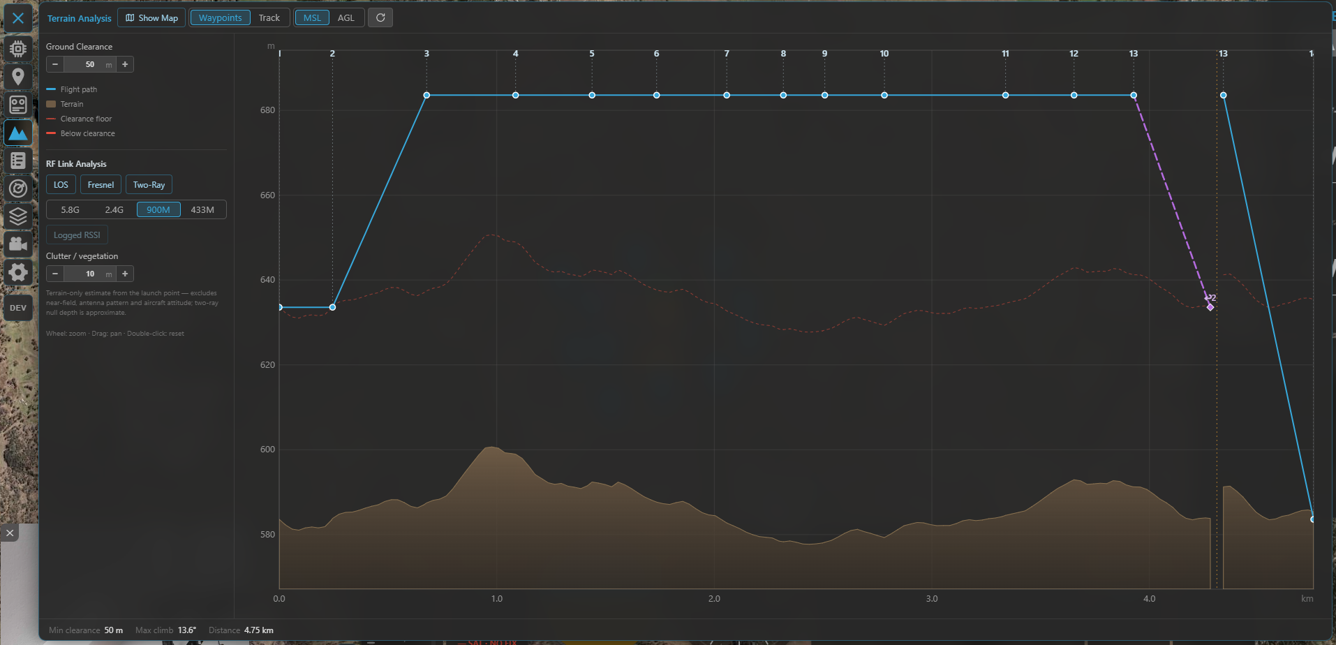
The profile: your path (blue) over the sampled terrain (brown), with the clearance floor and any below-clearance stretch flagged.
The chart draws:
- Flight path (blue) — your mission/track altitude.
- Terrain (brown fill) — the sampled ground.
- Clearance floor (dashed) — terrain + your Ground Clearance target; any path stretch that drops below it is drawn as a red below-clearance segment.
- Logged RSSI (Track mode only, when present) — see Track mode.
Below the chart the readouts show Min clearance (⚠ when it breaks the floor), Max climb angle and Distance. Moving the cursor over the chart adds a live readout of distance / terrain / altitude / clearance at that point — and a marker on the map.
Zoom with the wheel, pan by dragging, double-click to reset. The first and last waypoint sit slightly inset from the edges so their numbers stay readable.
Ground clearance
The Ground Clearance stepper sets the minimum above-ground height you want to keep. It drives the clearance floor (and the below-clearance highlight), and is the target used by Terrain Correction.
Terrain correction (Waypoints mode)
Beyond showing clearance, the tool can adjust your waypoint altitudes to hold the Ground Clearance target — for all three flight stacks. Pick a mode:
- Off — display only.
- Follow — set every waypoint in range to the target above-ground height, then raise any leg that would still clip the terrain.
- Check — only raise waypoints that sit below the target; never lower them.
A green dashed line previews the corrected path. The panel reports Changed (how many waypoints move) and the resulting min clearance. Tune it with:
- Range (WP) — limit the correction to a waypoint-number range. It defaults to the whole mission and stays that way unless you narrow it.
- Fixed-wing — additionally cap the climb / descent angle, raising the lower end of any leg that would be too steep for a fixed-wing aircraft.
- ➕ Add WP — click the chart to drop a marker on the path (a pin appears on the map), then add a waypoint there — e.g. on top of a ridge — and re-run the correction so the path hugs the terrain more tightly.
Press Apply to write the new altitudes into the mission. Two honest limits are surfaced rather than hidden:
- "Climb-angle limit forces some waypoints above the target clearance" — the fixed-wing angle cap won.
- "A leg between fixed waypoints stays below clearance" — that leg can't be cleared by moving one end (raise the fixed waypoint, widen the range, or add a waypoint).
How the corrected altitude is stored
INAV stores corrected waypoints as AGL (resolved to an absolute height from the terrain at upload). ArduPilot / PX4 store them in the terrain frame — the aircraft follows them as intended only with terrain following / a terrain database enabled on the flight controller.
RF link analysis (MSL view)
The RF section estimates where terrain shadows the radio link between the aircraft and the GCS, sampling the ground radially from the launch point. Turn on one or more methods:
| Method | What it models |
|---|---|
| LOS | Pure geometric line-of-sight: is the straight path blocked by terrain? (naïve on/off) |
| Fresnel | Knife-edge diffraction loss (ITU-R P.526) — a realistic, continuous loss that also covers partial blockage. Supersedes LOS when both are on. |
| Two-Ray | Ground-reflection multipath — interference lobes and nulls (mostly at the low bands, over flat terrain, at long range). |
Pick the band your link uses — 5.8 GHz / 2.4 GHz / 900 MHz / 433 MHz — since wavelength drives both diffraction and reflection.
- In the MSL view the result is drawn as a loss rainbow behind the profile (green = clear → red = heavily attenuated) and as coloured shadow wedges on the map.
- In the AGL view only the sightline-clearance line is drawn (the rainbow is MSL-only — a note reminds you).
Extra controls:
- Clutter / vegetation — a height added to the bare terrain for the obstacle analysis (forest, small buildings). It tapers to zero at both endpoints (you launch from a clearing; the aircraft is airborne), so only clutter in the path interior blocks.
- Logged RSSI — overlay the link strength actually recorded along a flown track (Track mode; enabled only when the track carries RSSI), to compare the model against reality.
The origin (GCS antenna) is the launch point / FC home / ArduPilot takeoff waypoint in Waypoints mode, and the first fix in Track mode. In Waypoints mode with none of those set, a hint asks you to anchor it (a wrong origin would give misleading shadows).
What the estimate is — and isn't
This is a terrain-only estimate from the launch point. It excludes near-field effects, antenna pattern and aircraft attitude, and the two-ray null depth is approximate (the lobe positions are the trustworthy part). Treat it as a planning aid, not a link budget.
Track mode
Track mode profiles a flown flight instead of a plan:
- Live — while connected, the current flight's track streams in and the profile extends in real time. A Follow toggle keeps the view pinned to the latest fix.
- Loaded — open a flight from the logbook (or a blackbox/log) to analyse it after the fact.
If the track carries logged signal strength, the Logged RSSI line plots it along the route, and (in the RF section) you can compare it against the modelled link.
Map view: the chart on the map
Show Map switches the panel to a wide strip so the 2D map stays visible next to the profile. This ties the two together:
- Hover the chart → a dot tracks the matching point on the map.
- Click the chart → a pin drops on the map at that point (it stays put even after you close the panel) — the same pin used by Add WP.
- With RF analysis on, the shadow wedges are drawn on the map where the link is degraded, pointing out from the launch origin.
So you can read "this dip in clearance / this radio shadow is there on the ground" at a glance.